Air–Water Hexarotor AUV
Six-DOF hexarotor that flies, dives, and changes shape in between. The arms retract and the props fold under water drag, so one airframe runs efficiently in both mediums.
- Role
- Mechanical design lead
- Organisation
- UCLA Mechatronics & Controls Lab
- Dates
- May 2026 – present
- Status
- In development
- Tags
- SolidWorks · Mechanism design · Waterproofing · ANSYS Fluent CFD
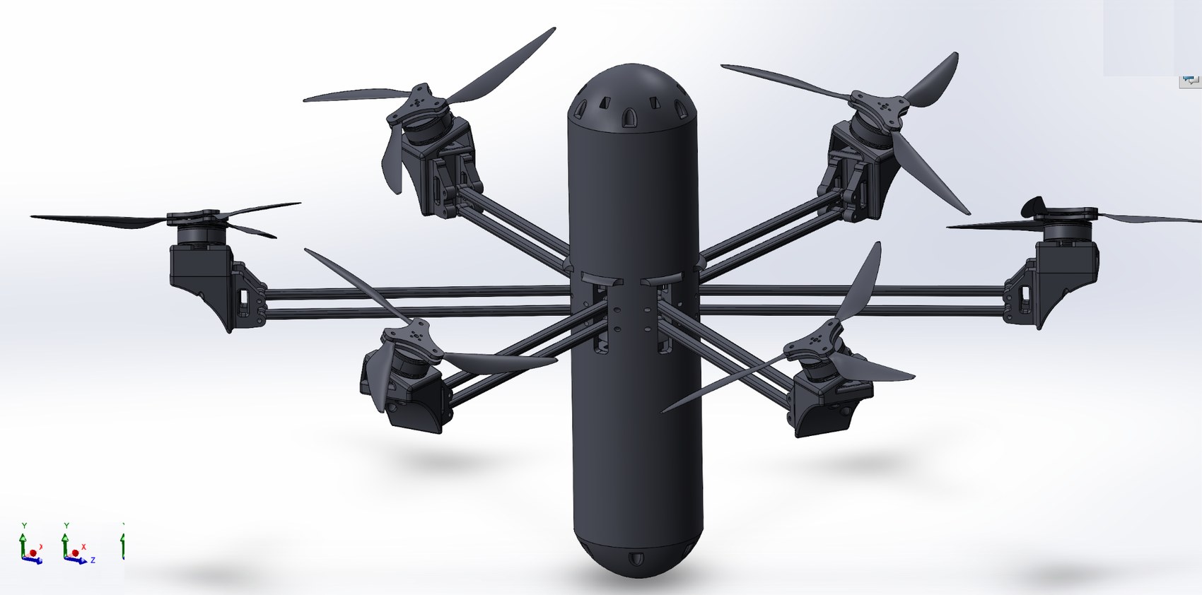
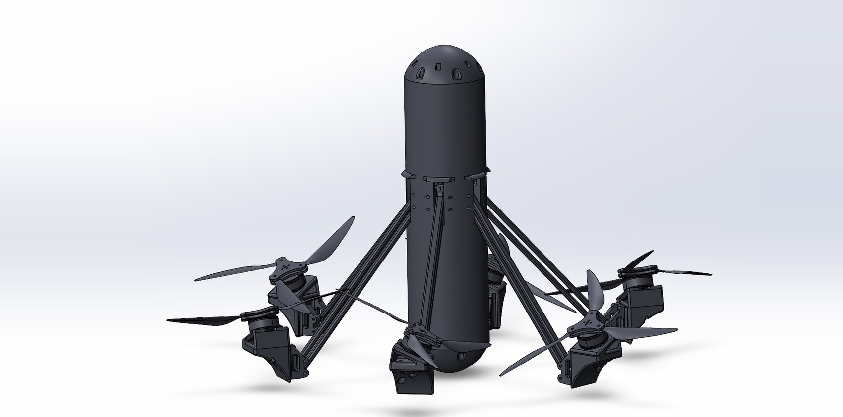
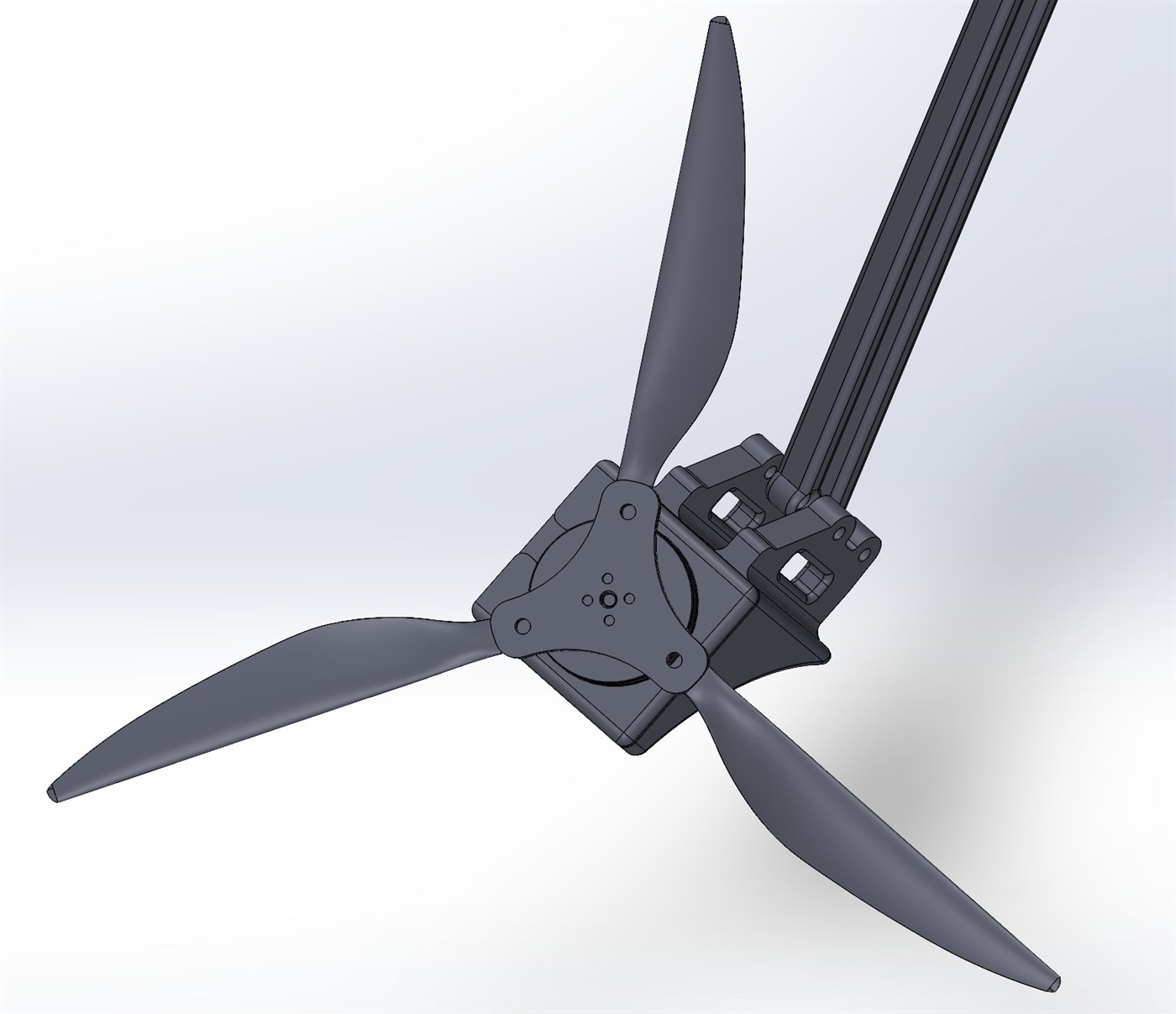
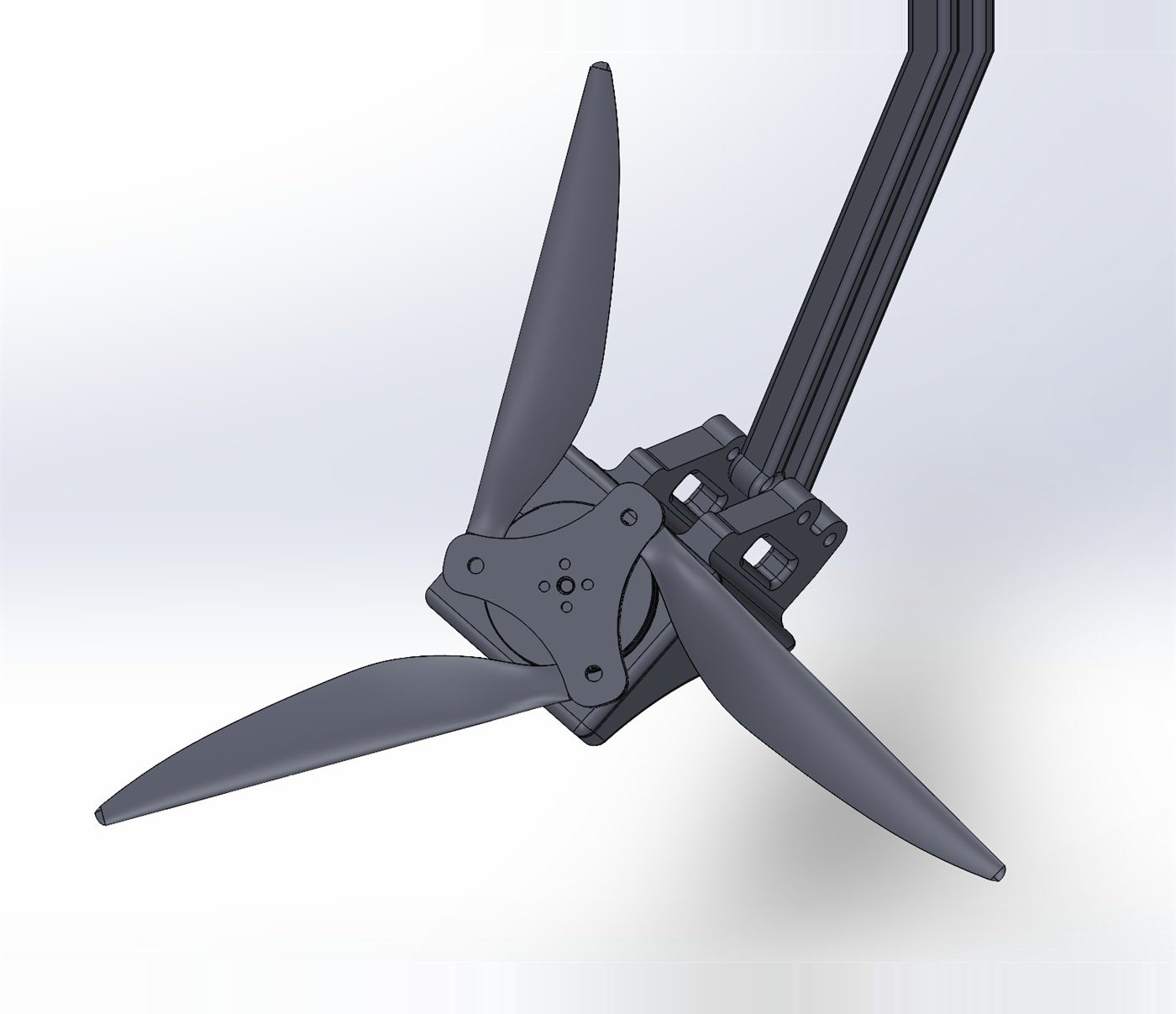
Arms extended, props at full span. Maximum disc area for lift.
CAD states of the same airframe. One lead screw drives all six arms; the props need no actuator at all.
- Configurations
- Air (extended) / water (retracted)
- Control
- Full six-DOF in both mediums
- Hull
- Three bays, five printed sections, o-ring sealed
- Actuation
- Single lead screw, six arms
- Progress
- In manufacturing — CFD running alongside
- Tools
- SolidWorks, ANSYS Fluent, Flow Simulation, FDM printing
Why it exists
Underwater infrastructure inspection — pilings, hulls, dam walls, intake structures — is still largely a diving job, and diving is the dangerous part of it. The vehicles that do exist pick a side: an underwater hull cannot fly, and a multirotor is a poor submarine.
A single vehicle that flies to the site, enters the water, inspects, and flies back out removes the boat, the tether, and the diver from a routine job. The same capability applies to survey, sampling, and filming across a shoreline.
Requirements
Full six-DOF control in air and in water, with a transition between the two that does not require the vehicle to be recovered and reconfigured. Survive extended submersion. Stay manoeuvrable enough to inspect at close quarters, where a drifting vehicle is a liability.
My role
I own the chassis architecture and the full CAD. The mechanical subteam lead directs me and two other members who own waterproofing and simulation; because I designed the geometry, I have been involved in both and run my own simulations. I work directly with the electrical subteam to package their custom boards into the sealed bay.
How it works
The hull is three bays stacked in line: a sealed electronics bay on top, a flood bay in the middle, and a battery bay below. The flood bay is exactly what it sounds like — it fills with water on submersion, which means it does not have to be sealed, and it is where the arm-retraction drive lives.
A lead screw in the flood bay drives a plunger fixed to the screw nut. The plunger face is profiled to match the arc the arms sweep, so it stays in contact through the whole stroke and pushes all six arms down and inboard at once from one motor. Retracting the arms shrinks the frontal area and pulls the motor pods in toward the hull, which is where most of the underwater drag was coming from.
When the vehicle leaves the water, the flood bay drains by gravity through its own ports. The props fold passively: water drag folds the blades inboard, and in air centripetal force throws them back out to full span.
Folding propellers
The same six motors have to work in two fluids, and the right propeller for one is the wrong propeller for the other. This is the part of the design I care most about, because it buys the vehicle a huge amount for almost no mechanical cost.
In air the blades sit at full span. That is what the aircraft needs to fly: the larger the swept disc, the more thrust a given motor produces, and every bit of it matters when the airframe is carrying a sealed hull, a flood bay and a battery.
Underwater that same geometry turns into a liability. Water is roughly eight hundred times denser than air, so a full-span blade at flight speed is trying to accelerate far more mass. The load on the motor climbs, current climbs with it, and a motor held in that condition overheats and burns out. On top of that, the extended blades add drag the vehicle has to fight the whole time it is submerged.
Folding the blades inboard against the pod fixes both at once. The swept disc shrinks, so the motor sees a load it can actually turn without cooking itself, and the frontal area dragging through the water drops with it.
None of that is actuated. Water drag folds the blades on entry, and in air centripetal force throws them back out to full span. No servo, no sensor, no control logic — the medium does the switching.
Key decisions
Fixed geometry vs. a hull that changes shape
- A purpose-built underwater hull — efficient submerged, will not fly
- A conventional multirotor frame — flies well, high drag and poor handling submerged
- A radially morphing frame — one airframe, two geometries
Radially morphing frame. Pressure sensors detect entry into water and trigger the transition.
The arms are parallelogram linkages, so the motor pods hold their angle through the full stroke and the thrust vectors stay valid in both configurations — retraction changes the footprint, not the control model. The lower link extends into the hull, where the arc-profiled plunger on the lead-screw nut drives all six arms simultaneously from a single actuator instead of six.
Two thrust systems vs. one that folds
- Separate air props and dedicated underwater thrusters
- A single compromise prop sized between the two
- A passively folding prop
Passively folding props on the existing six motors.
Long props make excellent thrust in air, and in water they overload the motors to the point of burning them out. Two thrust systems solves that with mass, cost, and a second set of motors — and six-DOF already requires six. The folding prop lets the medium do the switching: water drag folds the blades inboard so the motor sees a smaller disc, and centripetal force extends them in air. No actuator, no sensor, no control logic.
How to actually build the hull
- Machined aluminium — impractical at this size, heavy, bad for the buoyancy budget
- Carbon fibre layup — mould cost and lead time
- One large 3D print — exceeds the bed, and seals the bays permanently shut
A five-part printed hull, joined with o-rings and screws.
Every section fits the printer, and each bay opens independently for electronics swaps, maintenance, and re-sealing. It also concentrates the waterproofing problem into a small number of defined joints rather than spreading it across one large uncertain surface.
CFD — where the drag actually comes from
The first full study is finished: the smooth hull, solved in ANSYS Fluent. It exists to answer one question before the morphing mechanism gets judged on anything — on the bare vehicle, which surfaces are paying the drag bill? Until that is broken down surface by surface, “reduce drag” is a slogan rather than a design instruction.
- Solver
- ANSYS Fluent 2026 R1 — 3D, double precision, pressure-based
- Turbulence model
- SST k-ω
- Mesh
- 775,094 polyhedral cells
- Min. orthogonal quality
- 0.10
- Geometry
- Smooth hull, split into named wall zones
- Reported
- Pressure and viscous force per zone, resolved on the vehicle axis
The drag budget, surface by surface
Splitting the hull into named wall zones before solving is the whole trick — it turns one drag number into an itemised bill, and the bill is what tells you where design effort is worth spending.
| Surface | Pressure (N) | Viscous (N) | Total (N) | Share |
|---|---|---|---|---|
| Nose dome | −0.927 | −0.048 | −0.975 | 40% |
| Tail dome | −0.661 | −0.025 | −0.686 | 28% |
| Centre barrel | +0.001 | −0.364 | −0.363 | 15% |
| Water inlets | −0.138 | −0.014 | −0.151 | 6% |
| Flood bay | −0.142 | −0.002 | −0.144 | 6% |
| Screw holes | −0.118 | −0.002 | −0.120 | 5% |
| Arm slots | −0.013 | −0.002 | −0.015 | 1% |
| Resolved across these seven | −1.998 | −0.457 | −2.455 | 100% |
Three things fall straight out of that table.
The domes are the vehicle. Nose and tail together are about two thirds of the resolved drag, and both are overwhelmingly pressure — form drag, not friction. That is a shape problem, and it is the one worth spending time on. Polishing the barrel would win almost nothing by comparison.
The barrel behaves exactly as a slender body should. Its pressure term is +0.001 N, effectively zero net form drag, and essentially all of its 0.364 N is viscous. Flow stays attached down the length of it. That is the result I wanted to see, because it says the basic hull proportion is not the problem.
The holes are not free. The flood bay, screw holes, water inlets and arm slots exist for flooding and assembly, not for hydrodynamics, and together they cost about 0.43 N — roughly 18% of the resolved total. Every one of them is a feature I chose, which means every one is a feature I can fair, countersink, or move.
What the flow is doing
The velocity field explains the flood-bay number. The bay traps a pair of counter-rotating recirculation cells; the water inside barely moves relative to the hull, so the vehicle is dragging a slug of near-stagnant fluid along with it. Turbulent kinetic energy is near zero over the smooth sections and spikes exactly at the shear layer across the bay mouth — the same story told a second way.
That is the most actionable finding in the study. It is a geometry problem with an obvious first move: fair the lip of the bay and shrink the opening to the minimum that still floods at the rate the air-water transition needs.
What this changes, and what is still running
The smooth-hull baseline is the reference everything else gets measured against. Three changes go into the next geometry revision on the strength of it: fair the flood-bay lip and cut the opening back to the minimum flood rate the transition needs, countersink or plug the exposed screw holes, and reprofile the dome radii — since two thirds of the drag is form drag at the ends, that is where a shape change actually buys something.
Still to run: the same case in air, and the retracted configuration in water. The number the whole morphing mechanism rests on is retracted-versus-extended drag in water, and it only means anything measured against this baseline. The same studies size the propulsion system and feed the neutral-buoyancy budget.
The cheap analysis came first and already exists: flood-bay displacement and a neutral-buoyancy budget straight out of CAD mass properties, which is a spreadsheet rather than a solver run.
This section is empty. Two or three specifics — a part that did not fit, an assumption that broke, a print that failed — will do more for this page than another paragraph of design description.
Overall dimensions extended and retracted, dry mass, flood-bay displacement volume, arm stroke length, target neutral buoyancy. All of these are already in the CAD.
Where it stands
CAD and design are complete. Manufacturing is under way, the vehicle is part-built, and electronics integration is in progress alongside it — none of that is finished yet. CFD is running in parallel to characterise drag and settle the buoyancy budget.
Once the build is complete: bench actuation testing, then air, then water, then the transition between them.